For high-volume production of thin film panels and label stickers made from polycarbonate (PC) or PET, die cutting remains the mainstream process for balancing efficiency, cost, and product consistency. As a professional OEM custom manufacturer from China with more than 20 years of experience in precision die cutting for thin film products, Spar Panel breaks down the core principles, production advantages, suitable product types, and key design and production considerations of die cutting in this article, helping you understand why the process remains irreplaceable in mass production.
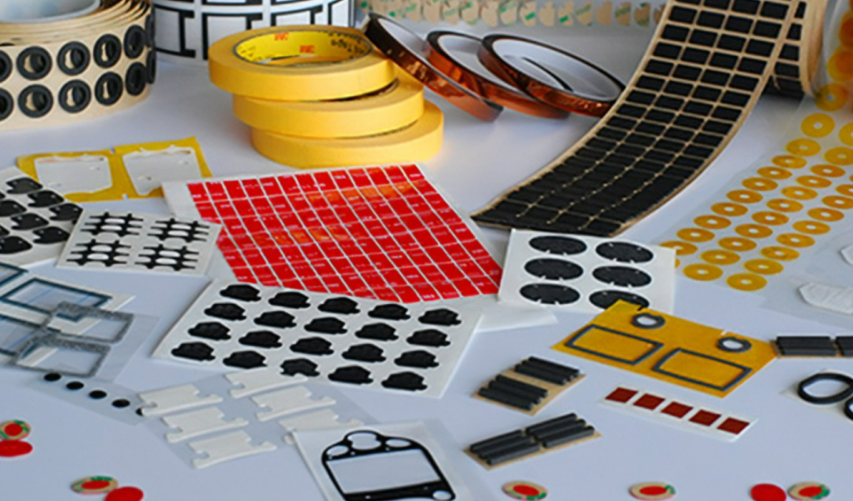
Die cutting is a converting process in which a custom cutting die applies pressure to sheet materials to shear them cleanly and efficiently into the required shape. It is widely used for high-volume converting of PET, foam, pressure-sensitive adhesive (PSA), and similar materials.
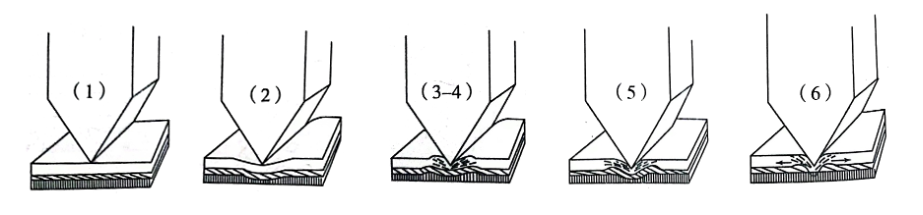
A typical die cutting cycle can be understood in six stages:
|
Diagram Label |
Stage |
Status Description |
|
1 |
Contact and Press-in |
The blade first touches the material surface and begins to apply pressure. |
|
2 |
Elastic Deformation |
The material is compressed within its elastic range, and stress gradually builds. |
|
3–4 |
Plastic Fracture |
Stress exceeds the yield limit, and cracks begin to form and propagate. |
|
5 |
Deep Cutting |
The cracks continue along the blade path, and most of the material separates. |
|
6 |
Full Separation |
The die reaches the bottom, the material fully separates, and elastic rebound occurs. |
Engineering tip: stages 3–4 are the critical window for cutting quality control. If pressure is too low, the product may not cut through completely. If pressure is too high, blade wear increases and die life is shortened.
Stable die cutting in mass production depends on close control of the entire converting workflow. At Spar Panel, the standard process includes the following five core steps:
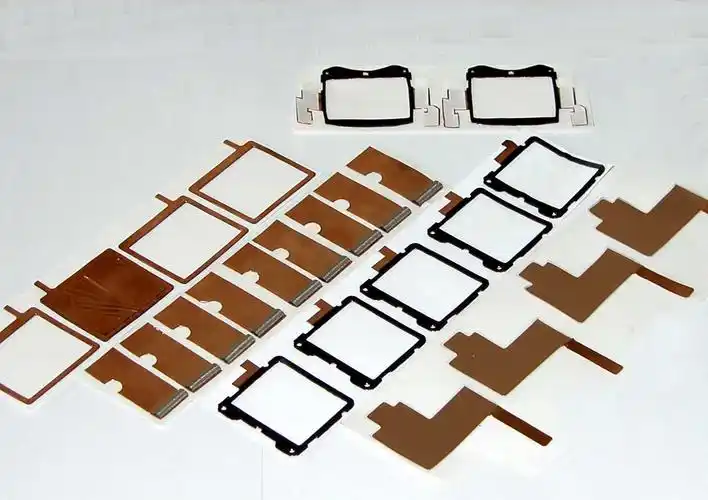
Die Design and Manufacturing: Our die supplier designs the cutting edge profile, blade height, registration method, and waste-removal structure based on your drawings. Nesting layout directly affects raw material utilization and final cost. Depending on accuracy requirements, wooden dies are used for standard tolerance ranges, while etched dies are used for high-precision thin film parts. Every die is trialed and verified before mass production.In panel manufacturing, die cutting is especially effective where high volume, repeatability, and low unit cost matter most. Based on material properties and production needs, the following four product types are typically the best fit for die cutting.
Typical applications include control panels for electronic equipment, touch windows, and instrument overlays. These products are usually made from polycarbonate (PC) or PET, with thicknesses concentrated in the 0.05–0.25 mm range. Our die cutting process offers strong edge control, with dimensional tolerance typically reaching ±0.1 mm. The cut edge is flat and burr-free, allowing the parts to move directly into assembly without secondary finishing.
These products are widely used for bonding, screen protection, and temporary process protection. Common materials include pressure-sensitive adhesive systems from brands such as 3M, Nitto, and Tesa, typically in the 0.02–0.3 mm range. Our mature kiss-cut process allows the adhesive layer to be cut accurately while keeping the liner intact, reducing the risk of waste breakage and adhesive residue.
This category includes product nameplates, operating labels, and brand identification parts, usually made from PC or PET with thicknesses from 0.08 to 0.8 mm. Stable registration enables contour tolerance to reach ±0.15 mm, allowing the cut edge to follow complex printed graphics cleanly and supporting a professional finished appearance.
These are key functional components used inside instruments, appliances, and other equipment. Typical materials include PORON and EVA, with thicknesses ranging from 0.3 to 5.0 mm. We provide customized converting solutions based on the required material, structure, and use environment.
The core strengths of die cutting are all tied to standardized mass production. For orders above 1,000 pieces, the overall cost-performance advantage is usually stronger than CNC cutting or laser cutting. The comparison below shows the main differences:
|
Feature Dimension |
Die Cutting |
CNC Cutting |
Laser Cutting |
|
Production Efficiency |
Extremely high; parts are formed in one press stroke during volume production. |
Low; the tool mills feature by feature. |
Medium; the laser head scans line by line. |
|
Unit Cost |
Very low after tooling cost is amortized. |
High. |
Medium. |
|
Consistency |
High; the die ensures repeatable cutting. |
High; controlled by program. |
High; controlled by program. |
|
Edge Quality |
Medium; strongly affected by blade condition. |
Excellent; polishing can also be integrated if needed. |
Medium; some materials may show melt marks or heat-affected edges. |
|
Initial Cost |
High; tooling is required. |
Medium; only programming is required. |
Low; only the drawing is needed. |
|
Design Flexibility |
Low; shape changes require new tooling. |
Very high; only the digital file needs to be revised. |
Very high; only the digital file needs to be revised. |
For relevant process details, please check our process service column.
Spar Panel has worked in precision die cutting for more than 20 years. As an experienced OEM custom manufacturer in China, we work with stable die cutting partners and have built a mature full-process production control system. Based on material characteristics, we can match the most suitable die solution for each project. Typical die life ranges from 500,000 to 1,000,000 strokes, and every die is trialed before mass production to help ensure clean edges without burrs or pressure marks.
As a global new-energy vehicle brand, Tesla maintains strict standards for compliance, process accuracy, brand consistency, and production stability across its supply chain. As an authorized global Tier 2 supplier for Tesla, Spar Panel custom-produces exclusive polycarbonate (PC) brand logo stickers for its in-vehicle and related products. By combining screen printing, adhesive lamination, and precision die cutting, we provide customized solutions that meet Tesla’s original factory requirements.
This case focuses on a custom polycarbonate logo sticker project we developed for Tesla in 2024. The product is mainly used in brand logo display areas of in-vehicle and related products. The core process is an integrated construction of back screen printing on a 0.2 mm frosted PC substrate, followed by 3M industrial adhesive lamination and precision die cutting. The project was managed through Tesla’s North American Tier 1 supplier. After multiple rounds of proofing and process verification, we met the customer’s requirements and achieved stable mass production.
To meet automotive supply-chain requirements and Tesla’s global brand standards, the project had to address four major challenges:
Drawing on more than 20 years of experience in precision die cutting, we developed a closed-loop production approach covering substrate adaptation, high-precision screen printing, process integration, and full-process quality control.
For the 0.2 mm frosted PC substrate, we used a dedicated high-precision etched die and optimized key parameters such as pressure, stroke, and cutting speed. Multiple rounds of die trials were completed before production release, helping ensure smooth edges without burrs or chipping while maintaining substrate flatness.
For Tesla’s brand graphics, we selected industrial-grade screen printing inks suitable for PC substrates and compliant with automotive interior environmental and weather-resistance standards. Tesla’s specified red and pure white were matched one-to-one and tightly controlled. The back-printing sequence was optimized so that the red base layer was printed first, followed by the white logo, reducing the risk of color bleed. Cross-hatch adhesion testing and high-low temperature cycling were also completed to verify long-term durability.
For the adhesive and die cutting combination, the full process was completed in a Class 10,000 clean workshop. High-precision automatic lamination equipment was used to control lamination tension and flatness, helping ensure the 3M adhesive was applied without bubbles, overflow, or warping. Registration between screen printing and die cutting references was also tightly controlled so that the cut contour remained centered to the logo while the release liner stayed intact for the customer’s automated mounting process.
Through multiple rounds of proofing and full-process optimization, we resolved the main challenges related to ultra-thin substrate converting, brand color control, adhesive and die cutting compatibility, and multi-supply chain coordination. The products passed the full audit of the North American Tier 1 supplier and Tesla’s terminal audit, and stable mass production was successfully launched. Yield remained above 98.5%, with zero batch quality issues, and delivery schedules matched the customer’s supply-chain planning requirements.
With stable process capability, a stringent automotive-grade quality system, and efficient supply-chain coordination, we earned recognition from both the North American Tier 1 supplier and Tesla. The project further reinforced our qualification as a Tesla global Tier 2 supplier and supported continued cooperation on Tesla interior logo and functional panel programs.
Please provide accurate vector drawing files in AI, PDF, CDR, or DXF format, and clearly indicate key dimensions such as the outer contour, hole spacing, locating edges, and tolerance requirements. Standard die cutting tolerance is typically ±0.2 mm. For PC/PET thin films using high-precision etched dies, tolerance can usually reach ±0.1 mm. For ultra-high precision requirements down to ±0.05 mm, feasibility should be evaluated based on material, geometry, die type, and registration method.
Tooling cost mainly depends on die type and product outline size. Etched dies are suitable for precision thin film parts. They can typically support tolerance around ±0.1 mm, while requirements down to ±0.05 mm should be evaluated case by case. Laser dies are suitable for standard-thickness materials and offer accuracy of about ±0.05 mm. Cost can often be reduced by optimizing nesting layout or by sharing tooling across products with similar outlines. Typical die life ranges from 500,000 to 1,000,000 strokes, which helps reduce per-part tooling cost in mass production.
The common tooling options are as follows:
For volume orders, tooling cost can be amortized effectively. Further savings can often be achieved through optimized nesting or by sharing a die across products with similar shapes.
For die cutting, the recommended thickness of PC and PET materials is ≤0.5 mm. Above this range, edge deformation or burrs become more likely after stamping. The minimum recommended inner-hole diameter is ≥1.0 mm, and the minimum recommended bridge width is ≥0.5 mm. Designs below these limits may lead to difficult punching conditions or a significantly shorter die life.
Recommended thicknesses for thin film substrates are shown below:
|
Material |
Recommended Thickness |
Typical Application |
|
PC (Lexan) |
0.125 mm / 0.188 mm / 0.3 mm |
Panels, identification labels, nameplates |
|
PET |
0.125 mm / 0.188 mm / 0.3 mm |
Membrane switches, decorative films, dustproof gaskets |
Spar Panel commonly uses the following double-sided adhesive brands, while other types can also be selected based on project needs:
|
Brand |
Typical Series |
Features |
|
3M (USA) |
467MP / 468MP / 300LSE |
High bonding strength and good temperature resistance |
|
NITTO (Japan) |
No.5000 / No.5600 |
Thin construction, suitable for precision die cutting |
|
TESA (Germany) |
4965 / 4970 |
High initial tack, suitable for curved-surface lamination |
Die cutting generally includes two cutting types: through cut and kiss cut. These should be clearly indicated in the drawing or technical requirements to avoid production ambiguity.
|
Feature |
Through Cut |
Kiss Cut |
|
Cutting Depth |
The die cuts fully through the material so that the part separates completely from the supporting substrate or waste. |
The die cuts only part of the material thickness, usually 50%–90%, while leaving the lower carrier layer intact. |
|
Final Form |
Individual parts are fully separated one by one. |
Multiple parts remain arranged on the full carrier substrate. |
|
Analogy |
Like cutting cookie dough with a cookie cutter to get separate cookies. |
Like the perforation around stamps, where each stamp remains attached to the full sheet but can be torn off later. |
|
Typical Application |
Independent gaskets, nameplates, identification stickers. |
Continuous labels, easy-tear stickers, and roll-fed delivery products. |
In short, die cutting exchanges higher upfront tooling investment for outstanding mass-production efficiency and very low unit cost. It is a representative process for high-volume, standardized production, especially for thin films, adhesives, insulation materials, and cushioning parts used in consumer electronics, home appliances, and automotive applications. For Spar Panel, it is one of the core capabilities that supports volume demand from well-known global brands.
Q1: What is the highest die cutting accuracy that can be achieved?
A: Standard die cutting tolerance is typically ±0.2 mm, while a high-precision etched die can reach ±0.1 mm. Actual accuracy depends on material characteristics and die type. Thin films such as PC or PET at ≤0.3 mm combined with an etched die are suitable for high-precision forming. For soft materials such as foam and adhesives, due to compression deformation, tolerance is usually recommended to be relaxed to ±0.5 mm.
Q2: What is the minimum size of the inner hole and narrow bridge position that can be achieved?
A: The minimum recommended inner-hole diameter is ≥1.0 mm, and the minimum bridge width is ≥0.5 mm. Below these limits, die strength drops, punching becomes more difficult, and die life shortens significantly. If the design must go beyond these limits, a precision etched die or laser cutting may need to be evaluated, and cost may increase by 30%–50%.
Q3: Will the edge of the die-cut product become fuzzy or deformed?
A: When the material thickness is ≤0.5 mm, edge quality is generally controllable. Above this thickness range, burrs or deformation become more likely. With a new die, PC or PET film can typically achieve edge roughness within Ra≤1.6 μm. After more than 300,000 strokes, blade condition should be checked and sharpening or replacement should be considered if necessary.
Q4: What is the registration accuracy of die cutting after printing?
A: Registration is usually controlled within ±0.15 mm and can reach ±0.1 mm for higher-precision applications. It is recommended to reserve a safety margin of at least 0.2 mm between the print file and the die cutting file to reduce the risk of exposed white edges or graphics being cut. For ultra-high precision requirements such as ±0.05 mm, process feasibility should be evaluated in advance.
Q5: How long is the service life of the cutting die? Do I need to share the tooling cost?
A: Etched dies typically last about 500,000 to 1,000,000 strokes, while laser dies typically last about 200,000 to 500,000 strokes. Thin film materials cause less die wear and therefore tend to reach the upper end of die life, while abrasive fillers or thicker materials increase wear. For mass production, tooling cost can usually be amortized effectively.
Q6: Is the bonding strength of the double-sided adhesive sufficient? Will it fall off?
If you have customized production needs for precision die cutting of thin film panels, label stickers and related products, please feel free to contact us and submit your design drawings. We will provide one-to-one process feasibility review and a detailed quotation service.


